Halloween, somehow, has become a big deal in our neighborhood. It started well before we moved in and has grown every since. Our all time record back in 2011 was 1200 visitors, 8 big bags of Costco Candy, 2 fire trucks and 8 firemen… (but that’s a different post).
Over the years, we’ve built up a hand full of fun and interesting props to use at Halloween. Some are easy to buy and surprisingly effectively, some took a month, CNC machinery, hundreds of dollars and me swearing that I’ll never do Halloween again.
Here is simple prop build that was surprisingly effective and inexpensive to build. The parts are easy to get if you don’t already have them already.
Radioactive Toxic Waste barrel
Back in 2012, we built out the set for a Toxic Waste Dump (in the front yard). Wildly successfully, we had everyone helping wear white Tyvek Hazmat suits – a very cheap and authentic costume.
The Radioactive Waste Barrel was built and put into the center of the display.
Parts
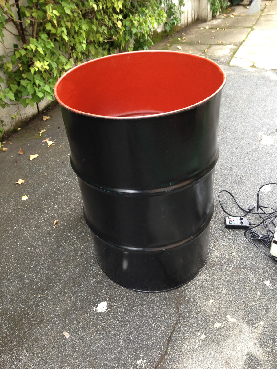
First, you need to find a barrel of some sort. We purchased a new 55 Gallon Steel Barrel, exactly what you would think would be used to store Radioactive waste (and, apparently, a favorite among home wine makers… who knew).
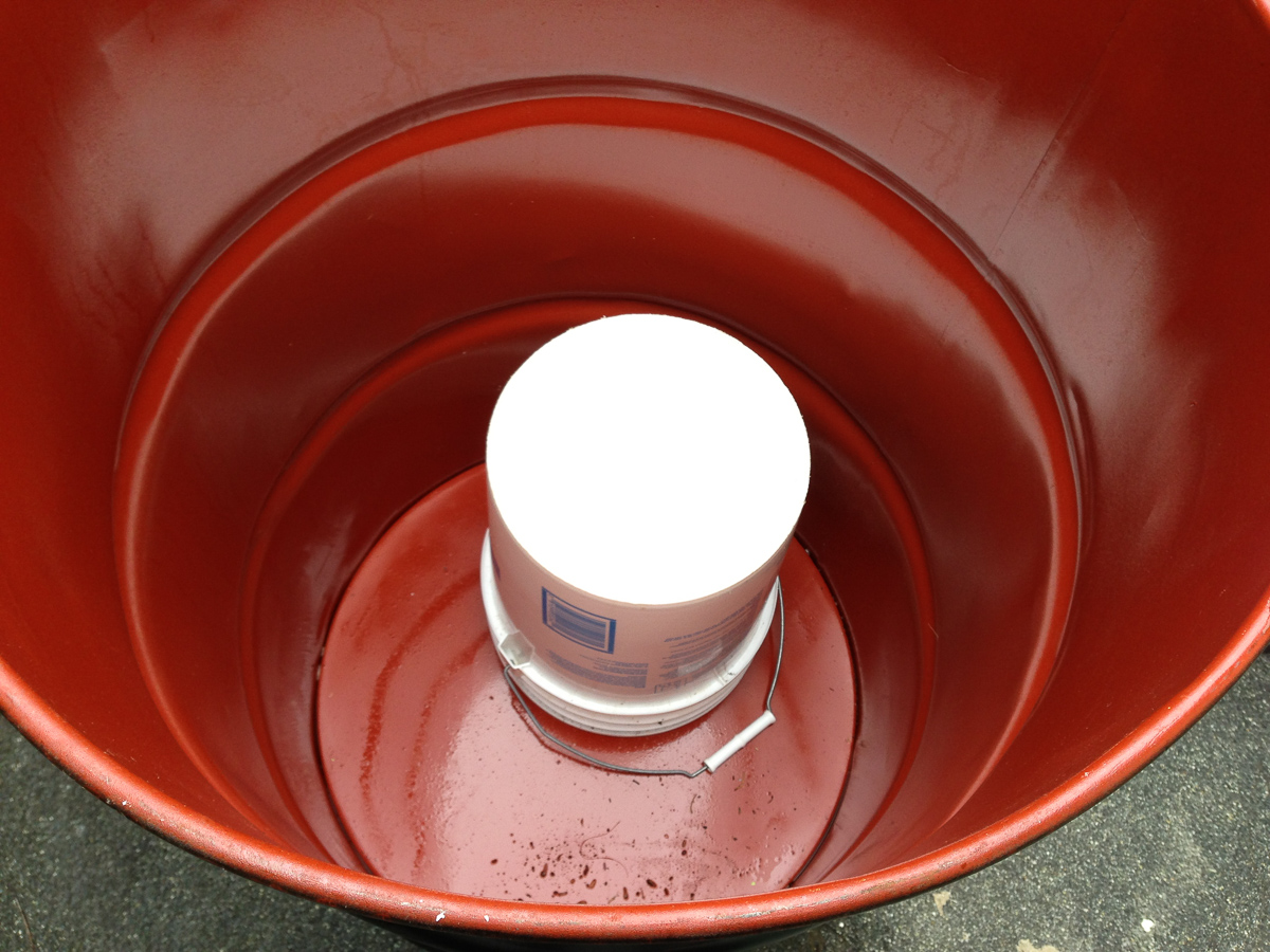
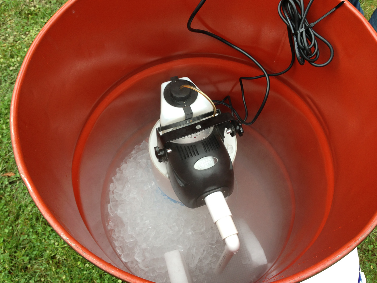
Next, you want to build a platform for the smoke machine, you want the smoke machine to be about mid way so that you can fill the botton of the barrel with ice and turn it into a huge fog chiller. That will keep cool the smoke down and give you the effect of thick smoke rolling over the edge and falling to the ground.
For this, I just used a plastic bucket.
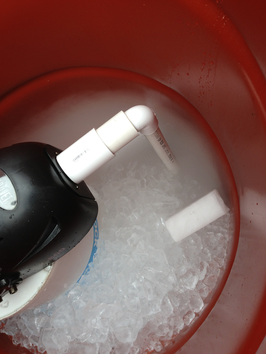
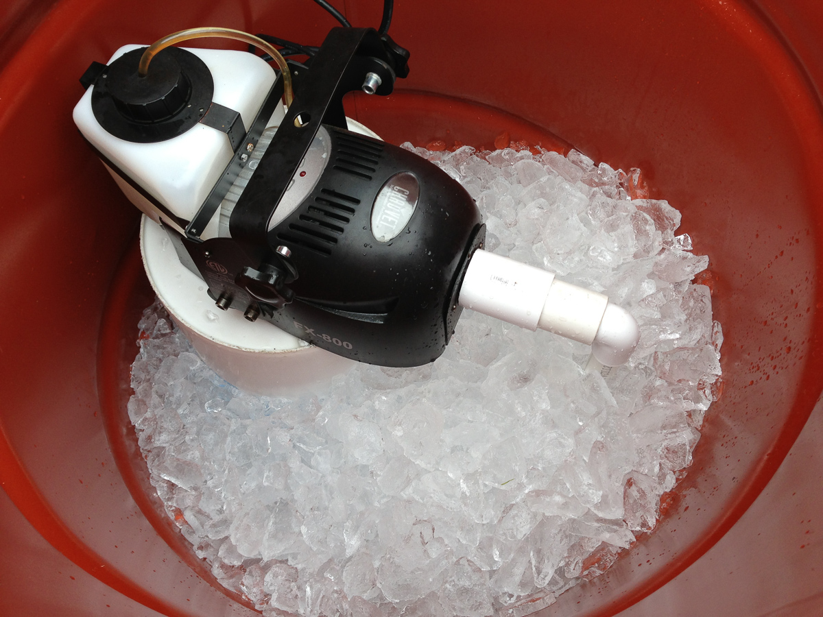
Next, you need a smoke machine. I used one of our small units that I could control with a timer to turn it on/off at a low frequency. If you use ice (you should) then, you want to get the smoke under the ice so that it can rise up through the ice and cool itself on the way up. Some PVC from Home Depot and electrical tape fixed that problem. Our smoke timer has magnetic strips on the back so easily attaches to the outside of the steel barrel.
Oh Halloween, start filling the barrel with ice.
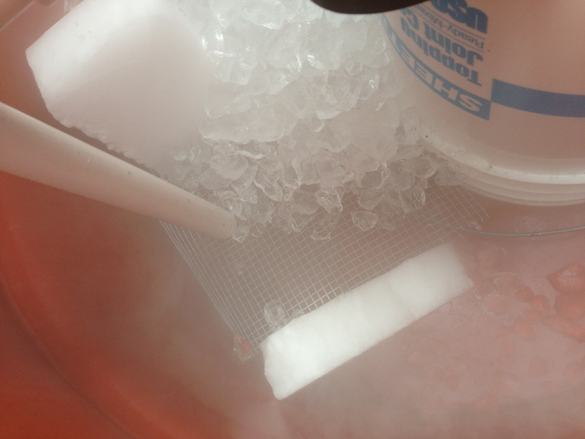
So, we did make one little optimization, we put down a screen and two blocks of dry ice that we had to spare. We were hoping that the smoke would hit the dry ice and cool itself further.
The screen is so that the ice can build a platform over the smoke. What will happen when you turn this on is that the smoke will quickly melt the ice together making a firm block. You want to avoid the situation of having the ice fall down melt around the pipe and then allow all the smoke to escape without being cooled. I think our solution worked okay, but could be improved, the easiest path for the smoke will certainly melt the ice around it. Perhaps dumping a few pounds of ice into the barrel every hour would help? But how has the time to do that with 1200 kids “asking” for candy?
So fill the rest of the barrel up with ice…
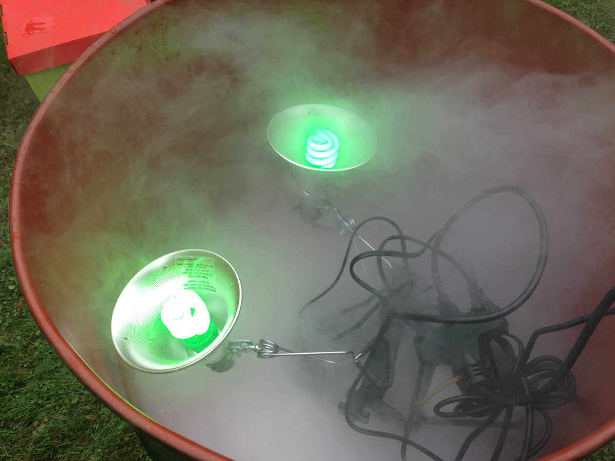
Now you need lighting. Two clamp lights from home depot with a pair of green fluorescent E26 bulbs is perfect.
That’s it!.
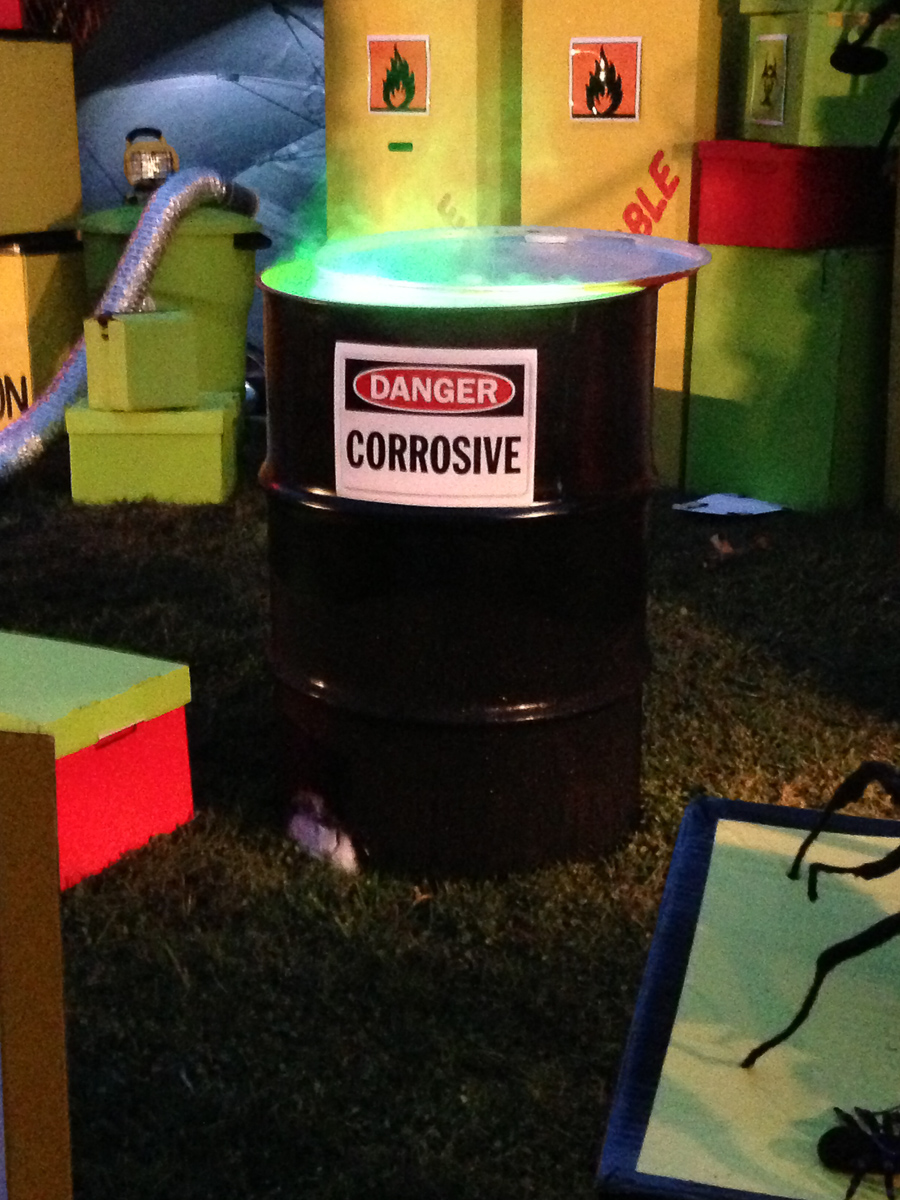
Put the lid back on to partially cover the barrel, turn on the timer to give occasional spurts of smoke, and this barrel will ooze radioactive waste all night.
(Oh yeah, print out a clever sign and tape it to the side of the barrel)
Two hazmat workers warming themselves up next to the radioactive waste barrel…
And finally, what does it really look like at night?
(the night before, no ice added, still looks good though).
This is a very quick project and is a device that I have been building for some time. It’s actually trivial in design, there is no complexity here, but I thought I would document this anyway since it uses some off the shelf parts to make a Lutron RadioRA lighting system control devices that it was never meant to control.
What is it?
Lutron makes a house lighting control and automation system called RadioRA, it’s a rather well designed system and I’ve been using the v1 since 1997. They have since updated it with a newer RadioRA2 system (which is far more capable and easier to program). RadioRA is designed to control lights. You replace your regular light switches with their RF enabled switches, and install control keypads into the wall which then talk to these RF switches. A control pad button can be programmed to make any number of switches set to a reprogrammed dimness value. It makes it very easy to quickly activate complex lighting scenes (where multiple dimmers are involved) with a press of single button. It’s great!
What RadioRA doesn’t do, is control anything other than lighting equipment (well, you can get them to control Lutron window shades…), which is rather unfortunate, because there can be useful scenarios where you want a non-lighting device to react in concert to a lightning scene change. One that I use often is to make my projection screen drop from the ceiling when I activate the “I’m about to watch a movie” lighting scene.
So how do we do this then?
Given the Lutron does not make a device that does this, we can easily build out own. Now, you might be thinking, wait, don’t they sell something like this? Partially. RadioRA1 had a table top dimmer module, the RA-300TL. This device is optimized for dimming lights, and there are several problems with using this to control appliances. First off, it is limited to 300W. Second, it has a slow voltage ramp up, so it won’t switch immediately to 120V, but instead ramp up over a few seconds. This is not really ideal with any electronic devices. And finally, it has dimming functions. Again, not ideal since you would never want this device to output any voltage other than full 120V. Finally, the RA-300TL is not a grounded device and not intended to power 3-wire (grounded) loads.
The Solution, DIY Lutron RadioRA Appliance Module
Combine a Lutron RA-8ANS Switch with a standard electrical outlet in a double gang box and add a faceplate. That will turn a Lutron switch into a standalone appliance module. Pretty easy and only takes a few minutes a bit of wire.
Lutron RadioRA DIY Appliance Module
Note: Lutron RA2 users already have a good solution, the Appliance Module, which effectively combines these two parts into one package. RR-15APS-1
I’ve been surprised as to how many applications I’ve found for these packages. From turning on audio amps in a room to standalone fans. It’s a good way to surface appliances to a Lutron keypad and be able to tell if that device is turned on or not.
This was a one night project; to build the ultimate high-powered air-assisted marshmallow shooter (well, or just a better one than the regular blow-gun style guns found everywhere). The shooter had to be used the next day in a shoot-out, so only one evening could be dedicated to design and fabrication. To keep things simple, I wanted to restrict the parts to standard PVC fittings available at Home Depot (with the one exception of the inner barrel, as you’ll see below). I also wanted to avoid any adhesives, glue, fasteners or taping in the construction. This was to save time and to make it easy to take the shooter apart for cleaning. Basically, it should be easy to put together and take apart.
Rewind two days…
For my daughter’s birthday, we set up a station where all the kids could build their own marshmallow shooters out of 0.5″ PVC pipe and fittings. This was a big hit at his year’s Maker Faire, and she wanted to do the same thing at her party. A quick trip to Home Depot, 80′ of PVC pipe, bags of connectors, and an hour with the miter saw, and we had all the parts for 30 shooters (oh, plus 5 rolls of patterned Duck Tape to decorate them).
It was a big hit, they worked well and the kids loved them, spending the afternoon shooting each other with mini marshmallows (that, or stuffing the marshmallows in their mouths as fast as they could before their parents found out). Either way, everyone left happy.
A few days later, I was to test my best design for a shooter against that of one of the party’s guests (who had a pretty good traditional shooter). Since the rules were, build the best shooter you could, I quickly decided to give myself a little “edge”, and build an air-powered shooter. But I also wanted to fix one glaring problem with the traditional PVC marshmallow shooters.
What’s the problem?
Here’s the design for a typical 0.5″ PVC marshmallow shooter found around the internet.
It’s made from 0.5″ Schedule 40 PVC pipe. 1×6″ pipe, 6×4″ sections, two T connectors, two elbows and two end caps. Put them together, and you have a marshmallow gun. It works well, but not fantastic.
Here’s the problem. The average size of a typical marshmallow is about 0.5″
(take this measurement with a grain of salt… this one just happened to be 0.5000″ on one side, some are larger, some are smaller, and they are very soft and compressible).
When you insert a marshmallow into the barrel of a 0.5″ PVC pipe, there is a pretty big gap between the marshmallow and the inside of the tube.
A portion of the air that is used to propel the marshmallow will escape around the projectile.
A barrel with a slightly smaller diameter would be ideal, and it turns out that one exists.
(also note, marshmallow diameter changes depending on freshness and duration of air exposure. The longer they sit out in the open, the smaller than diameter gets, they also tend to decrease in diameter after firing).
This tube looked perfect, but it’s just an acrylic tube, you still have to build an impressive shooter around it.
Fortunately, this tube fits (tightly) inside a 0.5″ PVC tube, allowing you to create a second, internal barrel.
The Prototype
Since the shooter will be air powered, it will get it’s air supply from a portable air tank. To test the new tube, we had to pick a nozzle for the air canister that we would use.
I tested various nozzles in the air gun, but the tiny orifices really resisted the volume of air that that was available. In the end, the best results were obtained from the largest opening, or no nozzle at all.
A few pieces of cut pipe, and we had ourselves a prototype:
This worked great, the marshmallow flew out of the barrel at high speed.
The Marshmallow Cannon
I figured the final design had to be be big and impressive looking, 1.25″ PVC was selected for the outer barrel. It allowed us to easily mount the new Acrylic Barrel inside and provided a substantial looking shooter.
For effect, I drilled out a series of “vent” holes in the barrel. Why? Well, every big cannon looking gun in the movies has them, so our shooter should as well.
Fortunately, the DRO on the milling machine made this a very quick operation. Eleven holes were drilled in three rows with a 1/4″ bit around the outer barrel.
The next thing we needed was a sight, and the ultimate in marshmallow sights has to be a red laser sight.
Fortunately, I just received a great little 4mw red laser module from All Electronics. It had a current limiting PCB attached, so you just powered it with 3V and it was good to go. For the power source, a 3V Litium CR123 battery was used. That should allow this to last for some time. I had a set of spring loaded CR123 battery terminals, and this allowed for the battery connections. For effect, a high-powered red LED was added to show that the laser was engaged.
The circuit is straight forward enough, 3V to the laser diode and the LED in parallel with a 30 ohm limiting resister.
All of this was packaged inside a section of 1″ PVC pipe. The switch was mounted into a 1″ PVC end cap.
A few inches of blue tape around the laser module made for a snug fit inside a small section of the same acrylic tubing that we were using for the main barrel.
The finished laser sight, with LED mounted at the top. Note, a #10 drill bit is the perfect diameter for a 5mm LED, and provides a very snug fit with no need for an LED holder or any glue to secure it.
The laser is mounted inside a short section of the same 5/8″ acrylic tube used for the inner barrel. It turns out it’s almost the same diameter as the laser module. A PVC reducer is used to mount that acrylic tube into the 1″ PVC tube that houses the laser assembly.
It works!
Now, on the main design. For a shooter of this size, we figured that two handles were appropriate to wield such a weapon.
The overall length of each section doesn’t really matter, you can make it any length, the key will be to in cutting the inner acrylic tube to fit inside your outer barrel.
The real challenge was in figuring out how to mount the acrylic tube inside the 1.25″ PVC tube. I thought of making some custom mounts on the laser cutter, but that would have extended the build time, plus, I liked the idea of being able to build this out of standard PVC fittings available at Home Depot. Turns out there was a solution with a creative use of fittings.
As I found out from the previous shooter, the barrel has to be easily accessible for cleaning. One wet marshmallow and you suddenly have sticky goo all over the inside of your barrel. Your shooter won’t fire again until you clean it out and fully dry the barrel. The barrel had to be easily removable but still secure and solid in the gun and quick to replace in the outer barrel.
I concluded that the acrylic tube should have two mounts, one at the front and one at the back. The front mount was use a 0.75″ to 0.5″ PVC reducer. It turns out that the external diameter of a 0.75″ PVC reducer is almost exactly the internal diameter of a 1.25″ PVC pipe. A few wraps of vinyl tape to increase the diameter, and we had a snug fit. The front mount shouldn’t be too tight, the inner barrel will be secured at the back, you want it tight enough so that it won’t move around much, but it should slide freely.
Here is the front mount:
A breakdown of what this is:
Assembled section on the left, and the parts, in approximate location, on the right. The acrylic tube fits snugly inside a short section of 0.5″ PVC, which then fits into the end of the 0.5″ to 0.5″ PVC reducer. All this center’s the acrylic pipe in the reducer, which then fits into the 1.25″ PVC outer barrel.
The back end was a little more complicated.
For this, we used a 1.25″ to 0.5″ reducer. The end cap had a hole that would allow the end of the air gun to fit securing to the opening.
Again, assembled part on the left, components on the right. From right to left, the acrylic tube fits inside a 2″ section of 0.5″ PVC, which then fit’s into the 1.25″ to 0.5″ PVC reducer, and finally a 0.5″ PVC end cap. The PVC end cap has a hole cut in it which allows our air gun to fit snugly into end cap.
Note, inserting the acrylic tube into the PVC fitting is a real paint, the acrylic is about 0.005″ too thick, which makes it difficult to insert. I tried sanding the ends down, which helped, but in the end I made them all fit together with the help of a very large rubber hammer. Try not to pound too hard as the acrylic can crack and shatter, unlike the PVC.
You want the tube length to be such that the back mount is secured into the outer barrel but it ends around the front of the barrel. Here is the tube mounted in the back:
The front:
The marshmallow is loaded from the end of the shooter, so the tube has to be about the same length as the overall shooter. It can’t be recessed too much into the outer barrel.
The entire tube with mounts:
Lastly, mounting the laser module. I used the quick and dirty solution of using two plastic cable ties to secure it. This has the added benefit of allowing you to adjust the aim of the laser sight by just nudging it.
The Completed Cannon
The air gun nozzle is attached to the air tank with some coiled hose, also purchased from Harbor Freight, but Home Depot sells this. I can’t recall where I got this particular air tank from, but you can use any, Home Depot, Harbor Freight and many stores sell a variety of tanks. Some quick connect fittings were used to tie the air hose into the tank and nozzle.
Testing the Cannon
So… does it work? Yeah, I’d say it does! Just follow the little red laser dot to see where it will hit.
Conclusion:
This design worked pretty well. Don’t expect a huge amount of accuracy from marshmallows, they tend to leave the barrel and arc widely to the left or right. I wore the air tank in a back-pack, and the entire rig had a “Ghost busters” sort of feel to it. The Laser site rocks. I’ve seen a design to build a enclosed air tank from large diameter PVC, if I were to make a V2, I would consider this option.
Marshmallow size varies dramatically. The best shots are from marshmallows that are exactly the same diameter as the inner barrel, and when inserted into the barrel, tend to slowly fall down the barrel.
You can use a wooden dowel to gentle push down larger marshmallows to the bottom of the tube.
The further you can push the marshmallow into the lower part of the barrel, the better it will fly. The worst shots were with marshmallows loaded into just the front of the barrel.
Tight fitting marshmallows tended to lose some diameter after being fired, which would them ideal for reuse.
After I built this, I found this very cool website that sells plans to build other marshmallow shooters, also out of PVC: http://www.myaircannons.com
Breakdown
Build Time
~ 3 hours
Total Time
1 day
Cost
~ $25 (not including the tank)
Difficulty (1 to 10)
2 (all you need is a saw, a drill and a bag of marshmallows)
For everyone in the San Jose area, I’ll be giving a lecture titled, Maker: The Art of Making at the San Jose April Pecha Kucha event on April 17th. This should be a fantastic evening.
This is a project that I finished up about a year ago and was the main motivation for purchasing my milling machine (yeah, didn’t take much, did it). Finally, after 14 months of design, shopping for a mill, more design and fabrication, I completed my “ultimate” dish drying rack for the kitchen. If you factor in the mill, it’s probably the world’s most expensive drying rack.
Exactly what is the Problem we’re trying to solve here?
I have a drying area behind my kitchen sink, which is the perfect location for a dish drying rack. The space is 9.3” in depth and so requires a custom solution to full take advantage of it.
Years ago I build a wood rack for this area, and while it worked well at first and fit it perfectly in the area, over the years the constant wet environment had a damaging effect on the wood. It would turn black with mold, the pegs eventually rotted and broke off, and the wood rack itself was just disintegrating. A new rack was required.
My previous design worked well, and I was inclined to construct the replacement in a similar style. Basically, a set of 0.25″ pegs spaced 1.25″ on a 9.3″ base, connected to six additional and identical bases. The design was pretty straight forward. How hard could this be, right?
My first thought was to build this rack from a moisture tolerant wood, such as Teak or Mahogany, but concluded that any wood would eventually have the same problem, and I wanted something more permanent and a bit more modern in appearance.
This required an either a plastic or metal base. I ordered several samples of 0.75”x0.75” square rods of various materials for prototyping.
Material picked for the prototype included (from left to right), Aluminum, Stainless Steel, Brass, Acrylic and HDPE (High Density Polyethylene) (aka, cutting board plastic)
Stainless, while is looked great, would have made the rack heavy and was difficult to machine at the time. Brass was expensive and I didn’t want the yellow coloration. A prototype was made of aluminum, acrylic and HDPE. Acrylic was ruled out for various reasons (some of which I overcame in the 14months of R&D). Aluminum was a possibility, but the question of how do you secure the pegs in aluminum was an open question, as was discoloration from long term oxidation of the aluminum in a wet environments. The HDPE prototype worked well and allowed for a design with a friction fit for the rods.
One additional issue with an all metal racks would have been the need for a softer material where a delicate knife edge and porcelain dish would rest. I didn’t want to damage and dull my kitchen knifes by drying them while resting their delicate edges on a hard stainless or aluminum surface. Some prototypes where created that would put a thin layer of rubber or plastic over the metal, but that proved complicated. Note, since completing the rack a year ago, I have had positive experience with laser cutable rubbers, which would allows for easy fabrication of a soft surface (maybe in v2). This still left the problem of securing the pegs into a metal base. Investigation in welding and braising the rods to the metal bars didn’t yield good results (at least that I pull off).
In the end, HDPE was selected since it was easy to machine, lightweight would allow a secure friction fit of the rods to the material and was an acceptable surface for contact with delicate cooking tools (after all, you do cut on an a HDPE cutting board surface, so a knife should rest very well on it).
The next question was what material to use for the rods. Since Stainless steel was an early favorite, that material was selected for the rods. A prototype HDPE with Stainless Rods was created and looked and functioned well. I also prototyped with various rod thicknesses, but the one advantage that stainless gave is that I could use a thin diameter and have it still be ridged. 0.25” was selected.
It was around this time that I was looking for a used mill to add to the workshop, so the project was put on hold for a few months while a suitable milling machine from Craigslist could be located and purchased. I eventually settled on a used RF45 Clone from Lathemaster (ZAY7045). Add another few months to install a DRO with glass scales on all the axis.
Five 4’ rods of stainless were ordered as was a sheet of HDPE plastic. Cutting the HDPE was straight forward on a compound miter saw, but the stainless was a bit complicated. Using a parting tool on a metal lathe, I fabricated 68 4″ pegs.
One immediate problem with parting the rods on the lathe is that it left a very precise, if not razor sharp edge. I was concerned that this would prevent the bars from seating properly into the holes and scratch any dishes. Filing the edges did not sufficiently round the sharp edge.
The bars were reworked in the lathe to have a 45 degree relief on each edge. A rather time consuming operation to do twice (once on each end) on 68 bars.
With the bars completed, it was time fabricate the horizontal HDPE bases.
Several prototype were made to determine how much smaller the hold had to be in order to correctly give a very tight fit to the 0.25” bar in HDPE plastic. The rods were 0.250” and the correct hole diameter turned out to be 0.246”, or a D sized drill bit. This allowed the bars to be easily tapped into the holes for a secure fit.
The device on the left is a fantastic piece of tooling, it’s a 5-axis Milling Stop, which allows you to set a workstop, so that I can slide bar after bar into the vise, slide it against the workstop and have it be in the same location every time. I can’t recall where I purchased mine, but noticed that Enco now sells the same model.
After two hours, all six pieces were completed. Two additional holes were needed on each part side to allow pegs to secure each base to one another.
Completing the rack was a simple matter of tapping in the pegs with a plastic hammer. Once seated, the pegs remain very firmly in place.
I wasn’t sure how well the kitchen ware would stand up to being inserted into stainless bars, so elected to add 0.25″ screw caps on the top of the pegs. This provided a soft rubber surface for any delicate items that might come in contact with it. I ordered several samples, and elected for black ones with a 0.5″ length.
A final detail, rubber feet. I wanted the rack to be slightly higher than the surface to allow easy drying and evaporation of water trapped under the rack. Plus the feet help secure the rack in place.
Three different samples were ordered. Stainless screws were used in the correct size to secure the feet. (Note, this turned out to be a big mistake, more below)
And finally, the completed rack.
The completed rack in place.
One year later
The rack works flawlessly, after a year, with almost no signs of wear. Several of the rubber screw caps have become nicked from sharp knife edges. They are not a big deal to replace as they are very inexpensive, but I need to factor in replacing about two caps per year.
Far worse was my decision in rubber feet. While I did use a stainless screw to secure the feet to the base, the selected feet contained a zinc washer in their base. After eight months, the washer started to corrode. Unfortunately, white marble is very porous and soon I had rust stains deep within the marble top. After trying various remedies to remove the rust, the one solution that worked fabulously was a mixture of 1 part Marble Poultice and 1 part Ironout (thank you internet searches).
I’ve been using the rack minus the rubber feet for the past few months while I search for an alternate.
Conclusion
This project started 14 months ago, and took a bit little longer than I expected. Selecting, purchasing and repairing of the milling machine consumed a large portion of the time, as was the creation of many prototypes to select the final materials. I’m currently planning for V2, which would be machined from stainless bases and include a 1/8″ thick rubber surface, laser cut to the shape of the bases, to protect knife edges, but that’s another project.
Breakdown
Build Time
~ 8 hours over eight days (minus various prototypes)
I needed a desk for my eight year old. With daily homework, it was obvious that she needed a place where she could work on her own. After scouring the obvious sources (ie Ikea), nothing in her size fit in the space that we had available, so a custom build was the obvious answer, but I needed it fast.
I had seen some very cool double desk designs at DWR (the original desk is no longer carried, but a similar one looks like this). This allows for a parallel storage area directly under the top desk writing space. I decided that my design would incorporate this element.
Next, I wanted the front to have a rounded fitted feel, instead of a straight typical desk shape, so the middle of the desk would be inset a few inches from the edges.
Finally, I didn’t want to take up space for a desk lamp on the top surface, instead, electing to have the lamp base built directly into the the desktop surface. I picked a relatively inexpensive lamp from Ikea (the Antifoni) which has a simple peg interface into the base. This would allow me to separate the lamp from the base and build it directly into the desk.
Using CorelDRAW, a desk design was created. The basic size would be 36″ x 24″. Top of Desk 1 (topmost plane).
The design would use 1.5″ Stainless tubing as separators between each desk plane, and a single hole for a custom machined aluminum bushing for the desk lamp.
Both the desk Top and desk bottom would be routed on a ShopBot CNC router, to accommodate the stainless tubing separates, the bottom of the desk Top and the top of the Desk Bottom would be routed with the same file (actually, a mirror image of the file).
The design was then transferred to VCarvePRO to create toolpaths for the ShopBot using a 3/8″ carbide end mill.
I first though I would use an Appleply plywood and then apply a Formica top for durability, but the Formica turned out to be expensive and overkill for any use that a desk would reasonably sustain. I elected for a pre-finished 3/4″ Maple plywood from Macbeath Hardwood in San Francisco. The edges are not that great, so maple edging would be required to finish the desk.
Setup time took an hour, as I made several test cuts of both spacer holes and lamp holes to get a perfect fit. Since the stainless spacers are held in by a close tolerance friction-fit, getting the exact size of the hole right was critical. In the end, I only needed to tap each tube in with a hammer to set them. Hole are 0.5″ in depth (on a 0.75″ thick top).
ShopBot cut time was relatively quick, less than 10 minutes per sheet.
With accurate measurements of the lamp peg, an aluminum bushing was machined on a metal lathe to accept the lamp. A close fit tolerance of 0.005″ was used for a tight fit. This tight tolerance wound up significantly improving the performance of the lamp, as the original, as bought from IKEA, had a large amount of wiggle and wobble due to the base not being sized correctly for the lamp. With the proper sized hole, the otherwise inexpensive Ikea lamp actually feels very nice.
Separator legs were created by cutting down a length of 1.5′ 304 Stainless steel on a metal band saw and finishing on a grinder fitted with a wire wheel. The idea was that the stainless tubes would friction fit perfectly into the top and bottom and not require any additional adhesives or fasteners to keep the two table tops together.
The edge banding proved to be a bit of a hassle. The traditional “cheap” method of using a standard clothes iron didn’t work, as the inner curve of the desk front prevented any good head transfer with the large iron. Reluctantly, I bought a specialized edge-banding iron from Woodcraft in San Carlos, which has a tapered front edge that allowed me to make the tight curve.
Routing the edge triming on curved surfaces proved to be very difficult. I started with a plain edge trimmer, but that did not handle the inner curves. I then tried my Makita Edge trimmer with a 1/4″ bit, but again, any tilt of the router tended to gouge out too much material from the edge. I spent some time fabricating a custom guide to my edge trimmer, but in use, that did not prove to be too effective. In the end, a sharp utility knife and sanding block was required to get the edges perfectly beveled with the top. This one task, by far, consumed the most significant amount of time (about an hour just in sanding these two tops).
Here is a view of the finished top.
Top with stainless spacers inserted.
And fully assembled.
Table light bushing installed.
As for legs, the design called from similar 1.5″ stainless tube legs, but seeing that I wouldn’t get a chance to access a TIG welder for a while, I decided to temporarily use a set of Ikea legs for the bottom set of legs. Eventually, I’ll replace these with matching stainless legs.
Completed desk in place.
The lamp busing worked out better than I expected. It really made a huge difference.
And finally, the desk at use.
Conclusion
Overall, this project came off very well. The legs are an obvious improvement, but I need to brush up on my TIG welding skills first. Two more desks are planned for the office area and they will follow similar designs. The pre-finished 0.75″ plywood from MacBeath really cut significant time with this project.
It’s a build log of sorts. I like to build stuff, interesting things and very ordinary things, some very elaborate and others to just use around the house. One thing seems to be consistent, I don’t make it out to the studio (that’s the garage out back) until around midnight, where I might spend a few minutes or a few hours working on the current project.
In the past, I would send a build email to various friends when I completed a project, but over the years, some have asked for a more permanent location to these logs, and so MidnightStudio was created. I’m not a machinist, or even skilled in any building techniques, heck, I’m a software guy. These logs will only illustrate one way to solve a problem, the one I picked. Most likely, it’s not the best way to build it, hopefully it’s not the worst, but I’ll document those as well (there have been many).
I hope you find something useful, if not entertaining, here.


")
")
")
")
")
")
")
")
")
")
")
")
")
")
")
")
")
")
")
")
")


")
")
")
")
")
")
")
")
")
")
")
")
")
")